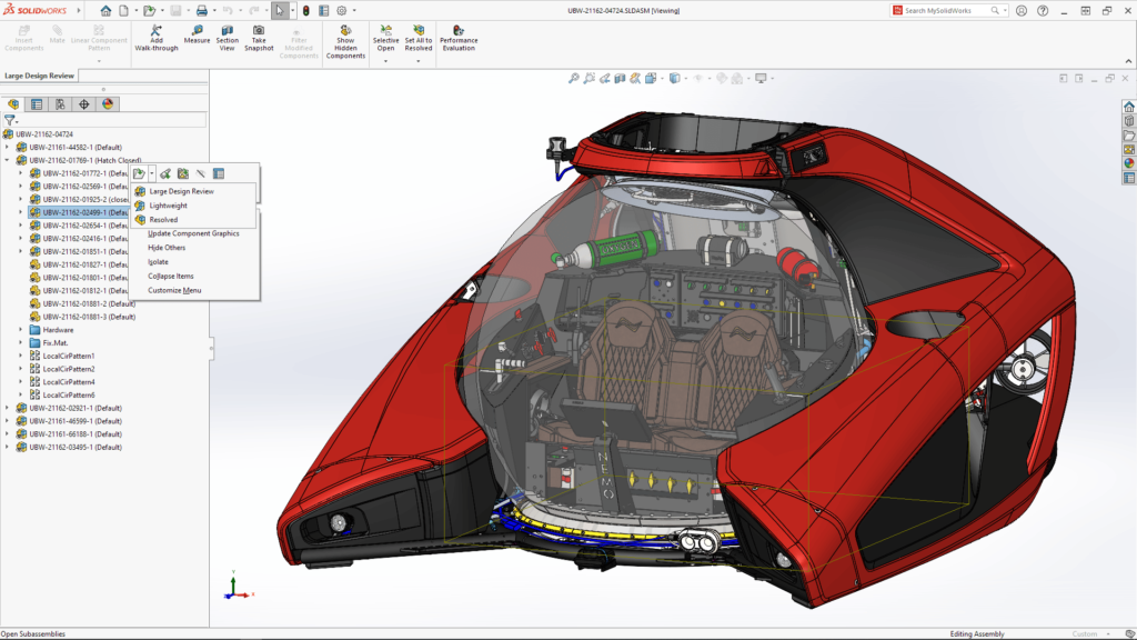
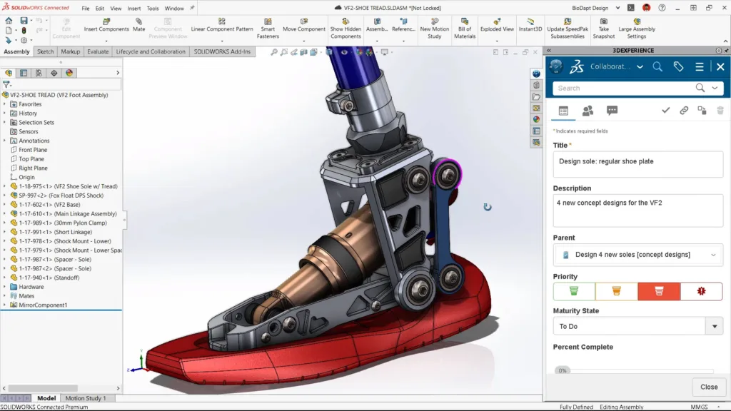
Solidworks is a powerful software used by engineers and designers to create 3D models and assemblies. One common issue that may arise when working with Solidworks is the need to unresolve components. Unresolving a component means that it is no longer fixed in place and can be moved or edited freely.
To unresolve a component in Solidworks, simply right-click on the component in the FeatureManager design tree and select “Float” from the context menu. This will change the fixed status of the component and allow it to be moved or edited.
It is important to note that unresolving a component may cause other parts of the assembly to become out of position. This is because the movement of one component can affect the placement of other components that are connected to it. To avoid this, it is recommended to fully constrain all components in the assembly before unresolving any of them.
To fully constrain a component in Solidworks, use the Mate tool to create relationships between it and other components. For example, you can use the Mate tool to align two components along a common axis or to create a distance relationship between them.
If you need to edit a component that is fully constrained, you can temporarily unfix it by right-clicking on it and selecting “Float”. After making your edits, you can then re-fix the component by right-clicking on it again and selecting “Fix”.
Unresolving components in Solidworks can be a useul tool for editing or moving parts of an assembly. However, it is important to fully constrain components before unresolving them to avoid causing other parts of the assembly to become out of position. By using the Mate tool to create relationships between components, you can ensure that your assembly is fully constrained and ready for editing.
Unmating Parts in SOLIDWORKS
In SOLIDWORKS, mating relationships can be created between parts to define their position and orientation. However, sometimes it becomes necessary to delete or unmate these relationships. Here are the steps you need to follow to unmate parts in SOLIDWORKS:
1. Firstly, locate the mate in the FeatureManager design tree. You can do this by expanding the tree and finding the mate, or by selecting one of the parts in the mate and using the “Mates” folder to locate the mate.
2. Once you have located the mate, click on it to select it. You can now delete the mate by using any of the following methods:
– Press the “Delete” key on your keyboard.
– Click on “Edit” from the main menu and select “Delete”.
– Right-click on the mate and select “Delete”.
3. A confirmation message will appear asking if you want to delete the mate. Click “Yes” to confirm the deletion.
4. The mate will now be removed, and the parts will be free to move independently.
It is important to note that when you delete a mate, it will only remove the relationship between the selected parts. If other parts were dependent on this relationship, they may also become free to move, which could result in unintended consequences. Therefore, it is recommended to review the entire assembly afer un-mating parts to ensure that everything is still in its proper place.

Unfixing a Component in SOLIDWORKS
In SOLIDWORKS, fixing a component means that it is locked in place and cannot be moved. However, this status can be easily changed if needed. To unfix a component, simply right-click on the component in question. This will bring up a context menu. If the component is currently fixed, you will see an option labelled “Float”. Select this option, and the component will become unfixed and able to be moved again.
If you prefer to use the keyboard rather than the mouse, you can also unfix a component by selecting it and then hitting the F key. This will toggle the fixed/float status of the component.
It’s worth noting that fixing a component can be useul for certain situations, such as when you want to ensure that it remains in a specific position relative to other components. However, if you need to move the component again, simply follow the above steps to unfix it.
In summary, to unfix a component in SOLIDWORKS:
– Right-click on the component
– Select the “Float” option
– Or, select the component and hit the F key to toggle its fixed/float status.
Undoing an Assembly
Unfixing an assembly in Fusion 360 is a simple process that enables you to move components withut constraint. To unfix a component, first, you need to right-click on the component(s) that you want to unfix and select “Float” from the drop-down menu that appears.
Note that if you move a component within a fully constrained assembly, the entire assembly will move along with it. However, any components that have not been fully constrained may appear out of position.
To avoid this, it is important to fully constrain your assembly before unfixing any components. Once you have finished moving the component(s), you can fix them back in place by right-clicking and selecting “Fix”.
In summary, to unfix an assembly in Fusion 360, follow these steps:
1. Right-click on the component(s) you want to unfix.
2. Select “Float” from the drop-down menu.
3. Move the component(s) as desired.
4. To fix the component(s) back in place, right-click and select “Fix”.
Unsuppressing Parts in SOLIDWORKS Assembly
When working with an assembly in SOLIDWORKS, it is common to suppress certain parts to make it easier to work with or to test different configurations. However, there may be times when you need to unsuppress all parts in the assembly.
To unsuppress all parts in an assembly, you can use the Unsuppress feature in SOLIDWORKS. Here are the steps to unsuppress all parts:
1. Open the assembly that contains the suppressed parts.
2. Click on the Features toolbar, then click on the Unsuppress button.
3. In the drop-down menu that appears, select “This Configuration” if you only want to unsuppress parts in the current configuration, or “All Configurations” if you want to unsuppress parts in all configurations.
4. Alternatively, you can choose “Selected Configurations” if you only want to unsuppress parts in specific configurations.
5. Once you have selected the desired option, SOLIDWORKS will unsuppress all parts in the assembly.
It is important to note that unsuppressing all parts in an assembly may caue performance issues if the assembly is complex or contains a large number of parts. In these cases, it may be better to unsuppress parts selectively, rather than all at once.

Conclusion
Solidworks is an essential tool for engineers and designers in creating complex 3D models and assemblies. Its user-friendly interface and extensive features provide a seamless and efficient workflow for designing and simulating parts and products. From creating basic sketches to generating complex assemblies, Solidworks offers a comprehensive suite of tools to meet the needs of any project. Its ability to integrate with other software and systems makes it a versatile and valuable asset in any engineering or manufacturing environment. Solidworks is a powerful and reliable software that continues to evolve and improve with each new version, making it a top choice for professionals in varius industries.
