Are you looking to understand the cutoff frequency formula? Are you a musician, engineer, or digital artist trying to learn how to craft beautiful sounds in the studio? If so, then you’ve come to the right place. This blog post will explain what cutoff frequency is and how it’s calculated using the cutoff frequency formula.
Cutoff frequency is an important concept when it comes to signal processing and sound design. It determines where a signal is cut off, meaning that frequencies above a certain value are filtered out. This can be particularly useful for creating desired sounds as well as removing unwanted noise from recordings. It’s also essential when creating synthesizers or effects processors as it determines the range of frequencies that can be used in a signal chain.
The cutoff frequency formula is used to calculate the exact value at which a signal will be cut off. It is given by fc = 1/(2πRC), where ‘R’ is the resistance of an RC (resistor-capacitor) circuit and ‘C’ is its capacitance. This equation can also be used to determine the phase angle of an output signal at Fc; for low pass filters this will always be -45o.
Knowing how to calculate your own cutoff frequencies can help you craft unique sounds and experiment with different tones. It can also alow you to create more complex effects processors by adjusting various values in your circuit. By understanding this concept, you’ll be able to control every aspect of your sound design process and create exactly what you want!
Understanding the Cutoff Frequency of a Filter
The cutoff frequency of a filter is the frequency at which the signal is attenuated, or cut off. It is the highest frequency that can pass through the filter before being filtered out. For example, if a signal contains frequencies from 20 Hz to 4000 Hz and the cutoff frequency of the filter is set to 2500 Hz, all frequencies above 2500 Hz will be filtered out. The cutoff frequency can be adjusted depending on what kind of sound you are trying to achieve.

The Cutoff Frequency of an RC Circuit
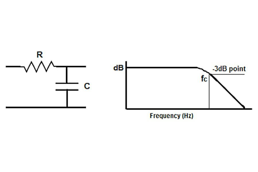
The cutoff frequency of an RC circuit is the frequency at which the output signal is reduced, or “cut off”. It is determined by the resistance (R) and capacitance (C) of the circuit, and can be calculated using the equation fc = 1/(2πRC). This frequency is important in determining how a low-pass filter behaves; when frequencies above fc are present, they will be lessened in amplitude as they pass through the filter. If the resistor and capacitor are exchanged within an RC circuit, it becomes a high-pass filter instead.
What is the Definition of Cutoff Frequency?
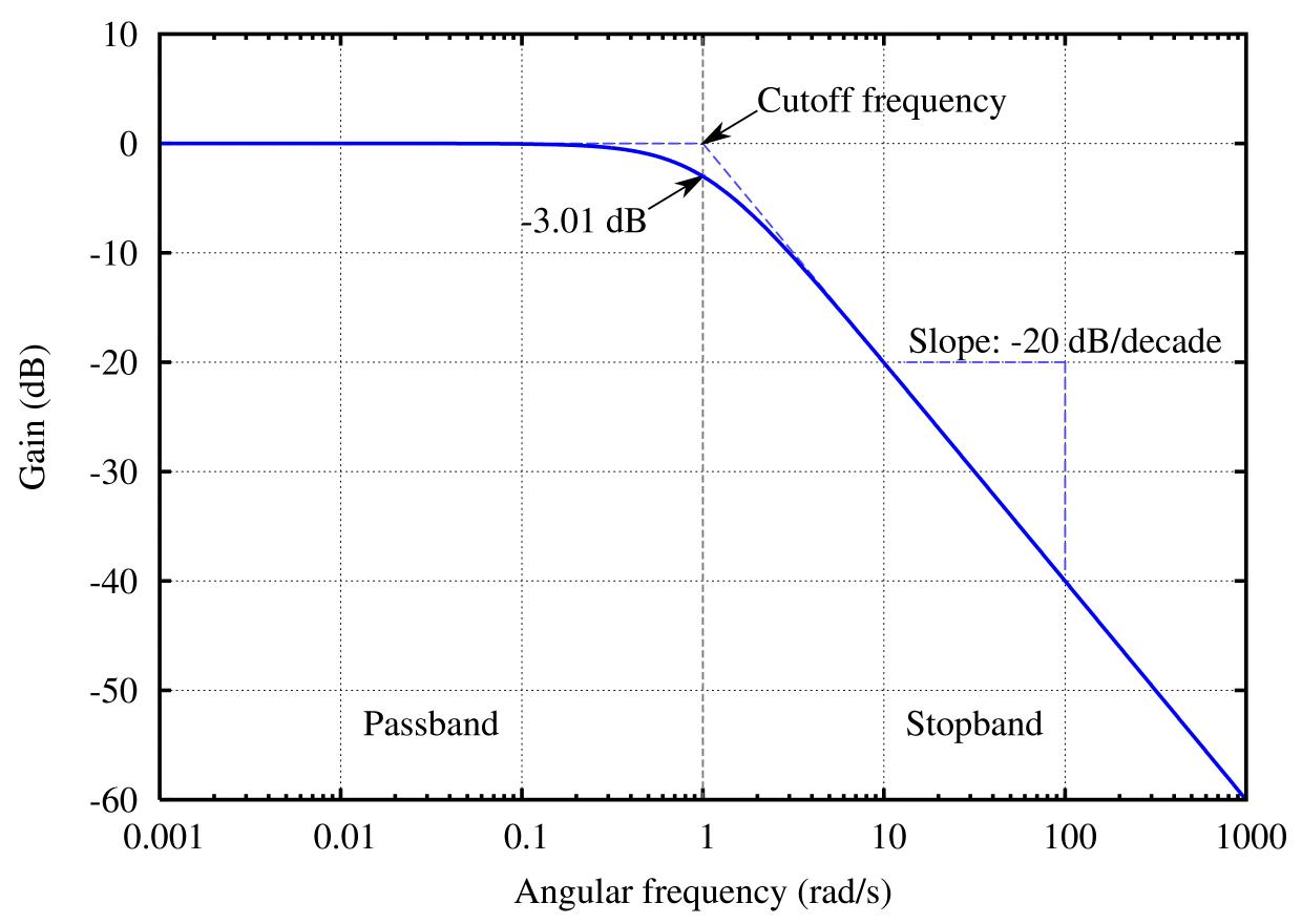
Cutoff frequency (Fc) is the frequency at which a low-pass filter’s attenuation begins to increase. It is defined as the frequency at which the gain of the filter drops off by 3 dB from its midband response, or at a defined frequency if the response is uneven. Above this frequency, the filter will begin to reduce the amplitude of any signals passing through it. Cutoff frequencies are used in applications such as audio filtering, signal processing and communications.
Formula for Cut Off Frequency in Low Pass Filter
The formula of cut off frequency in a low pass filter is ƒc = 1/(2πRC), where R is the resistance of the filter and C is the capacitance. This formula can be used to find the cut-off frequency or -3dB point for a low pass filter. The phase angle of the output signal at ƒc is -45o.
Understanding the 3 dB Cutoff Frequency
The 3 dB cutoff frequency is the frequency at which an electronic amplifier stage’s output power has dropped to half of its mid-band level. This term is also known as the -3 dB point, and it is used to denote the point at which a system’s signal has been attenuated by 3 decibels. In other words, the output power at this frequency will be half of what was measured at the mid-band level. The 3 dB cutoff frequency can be used to determine factors such as the gain or slope of an amplifier stage.

Is the 3dB Cutoff Frequency Universal?
No, the cutoff frequency is not always -3dB. This is because different types of filters use different criteria to define their cutoff frequency. For example, for a low-pass filter, the cutoff frequency may be defined as the frequency at which the gain has fallen to half its maximum value (or -3 dB), whereas for a high-pass filter, it may be defined as the frequency at which the gain has fallen to 1/10th its maximum value (-20 dB). It all depends on how the filter is designed.
Calculating Cutoff
Cutoff marks can be calculated by taking into consideration the marks obtained in Maths, Chemistry and Physics. First, the Maths marks are converted to 100, the Chemistry marks are converted to 50 and the Physics marks are converted to 50. This can be done by using a simple formula:
Maths (converted) = (Maths Marks/Maximum Marks) x 100
Chemistry (converted) = (Chemistry Marks/Maximum Marks) x 50
Physics (converted) = (Physics Marks/Maximum Marks) x 50
Once all the marks have been converted, they are added together to get the total cutoff mark. For example, if a student obtains 75 in maths, 70 in Chemistry and 60 in physics then ther cutoff mark will be:
Total Cutoff Mark = 75 + 35 + 30 = 140
This is how one can calculate their cutoff mark for admission into a college or university.
Understanding Cutoff Frequency and Bandwidth
Cutoff frequency is the point at which the output of a system begins to decrease, and is measured in hertz (Hz). Bandwidth is the difference between the upper and lower frequencies of a signal, also measured in Hz. The 3dB bandwidth is the frequency range between the point where the output of a system begins to decrease by 3 decibels (dB) and the highest attenuation point of that system. It is used to measure how much information can be transmitted through a given system, as well as how wide a range of frequencies it can handle.
Calculating RC Frequency
RC frequency is calculated using the following formula: 1/(2πRC), where f is the frequency variation, π is a constant with the value of 3.14, R is the resistance, and C is the capacitance of the circuit. The resistance and capacitance values are multiplied together and then divided by two times pi. This gives you an answer in Hertz (Hz), which is a measure of frequency. So, if you have a 10Ω resistor and a 1μF capacitor, your RC frequency would be calculated as 1/(2π(10*1E-6)) = 15915.5 Hz.

The Difference Between Cutoff and Threshold Frequency
Cutoff or stopping potential is the minimum value of negative potential at the anode which just stops the photoelectric current. It is usually measured in volts. On the other hand, threshold frequency is the minimum frequency of light below which no photoelectric emission will take place. It is represented in terms of Hertz or cycles per second. This means that if a photon has an energy lower than the threshold frequency, it will not cause any photoelectric effect.
Minimum Cutoff Frequency: An Overview
The minimum cutoff frequency for an air-filled rectangular waveguide is 15 GHz. This is the lowest frequency of the waveguide, and any signal below this frequency will be unable to pass through the waveguide. Above this frequency, signals can propagate through the waveguide, with higher frequencies producing lower levels of attenuation.
What is the Cutoff Frequency?
The cutoff frequency Mcq is the frequency below which a particular mode of propagation will not propagate in a waveguide. The cut-off frequency for a rectangular waveguide with dimension ‘a (length)’ and ‘b (width)’ is given as: f c ( m n ) = c 2 ( m a ) 2 + ( n b ) 2, where ‘m’ and ‘n’ are the mode numbers. The dominant mode in a particular waveguide is the mode having the lowest cut-off frequency. Therefore, the cutoff frequency Mcq is the lowest cut-off frequency among all the modes present in a waveguide.
Understanding Cutoff Frequency and Photoelectric Equation
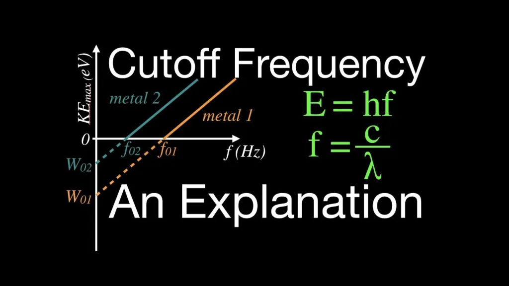
Cutoff frequency is the minimum frequency of a light wave necessary for the ejected electrons to have enough energy to escape from a metal surface. It is related to the work function, which is the minimum amount of energy required for an electron to escape from a metal’s surface. The cutoff frequency is calculated usig the equation fc=ϕh, where ϕ is the work function and h is Planck’s constant.
The photoelectric equation defines how light interacts with matter and how much energy each photon has when it interacts with matter. The equation states that the kinetic energy of an emitted electron depends on the frequency of incident light, and not its intensity. It can be expressed as Kmax=hf-ϕ, where h is Planck’s constant and f is the frequency of incident light while ϕ is the work function. This shows that when a photon strikes a metal surface, it transfers its energy to an electron on the surface which then has enough kinetic energy to escape if its greater than or equal to the work function.

Source: omnicalculator.com
Conclusion
In conclusion, the cutoff frequency formula is an important tool for synthesizers and other audio equipment. It determines where the signal is cut off and is calculated using a simple equation: ƒc = 1/(2πRC). The cutoff frequency is usualy defined as the point at which the gain falls off -3 dB from the midband response or, if the response is uneven, the response at a defined frequency. The phase angle of the output signal at ƒc is -45o for a Low Pass Filter. With this formula, we have a better understanding of how to control sound signals and shape audio.
